
Introduction
General overview
The project is aimed to control an indoor intelligent space where several Unmanned Ground Vehicles (UGVs) are simultaneously observed and controlled through a distributed vision system. The following figure shows the current setup in the University of Vigo where the different parts of the system can be identified.

The main parts of the system are:
- Localization system: It is composed by four camera-based localization nodes, each of which is made of a CMOS camera and an FPSoC development board. FPSoC contain powerful processor and FPGA in the same chip. In the current implementation the FPGA acquires images from the camera and preprocesses them, binarizing the UGV markers (geometrical shapes placed over the UGV top plate). The binarized images are passed to the processor which uses high level Python functions to extract the vertices of the markers. These vertices are sent to the main controller through the Ethernet LAN network. Apart from the vertices the nodes can also send the RGB, gray and binary images from the camera, useful for debugging purposes.
- The main controller consists of a CPU-based processing node that runs Python 3 software. Currently a PC is being used but the project is designed to be lightweight enough to be run in any embedded board like Raspberry Pi or (ZedBoard) that controls the whole system. The main controller is currently intended to be run in console. Currently the main controller can only control one vehicle at a time. The trajectory of the vehicle is defined by an array of points that the user types through the console. The UGV will pass through all of them in order doing rectilinear trajectories between them.
- The UGVs. The UGVs are small RC-like vehicles controlled by an Arduino board. The UGV has not intelligence, that is the controller is built in the main controller. The Arduino board receives motor speed workpoints through a Wifi-to-serial or Zigbee-to-serial Arduino shield from the main controller and sets the PWM of the motors to the corresponding values. The UGV has a battery system with custom PCBs to be able to charge the battery of the UGV (through or wirelessly) and measure the battery levels. Arduino board communicates periodically with the board measuring the battery level. The main controller can ask the battery level to the Arduino board also through the wireless protocols.
The main structure of the system can be observed in the diagram below:

Main controller
The main controller does:
- Communicate with the FPGA-based localization nodes, using the Ethernet LAN network, and asks the vertices of the markers in the field of view of the camera.
- It merges the data obtained from the localization nodes. In example, when an UGV is in the frontier between two cameras there are marker vertices from the same UGV in different cameras.
- Get the pose (position and orientation) of each UGV from the vertices location.
- Given the destination of the UGVs, calculate the optimal path. Now an array of points that the UGV should visit are passed through the console.
- Calculate the UGVs motor speed, using a navigation model, to pass through the set of points previously added via console.
- Communicate with the Arduino boards in the UGVs, using the Zigbee protocol or WiFi, and send them the speed set points of the motors.
- The main controller can also read the battery level of the UGV and prints it in console.
Apart from the main modules that implement the previously explained behaviour, the main controller has extra programs used to test and debug different parts of the system like the Kalman Filter developed or the navigation model. Some of these extra programs can be used to acquire images and video from the camera-based localization nodes.
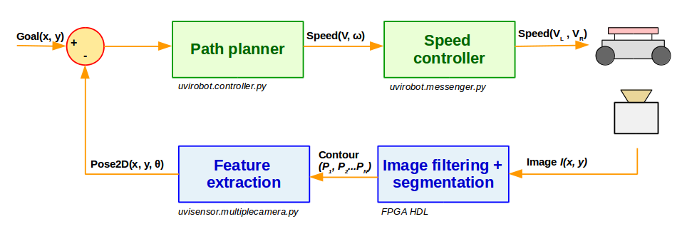
Regarding the control workflow, the system can be considered a closed loop, where the position of the UGV read by the cameras is fed back to the main navigator that, along with the goal position, are used to determine the speed output sent to the UGV. The corresponding diagram can be seen below.
Localization system
The localization system is one of the most innovative parts of Uvispace. It is composed by a Terasic TRDB-D5M 5MPix camera attached by a 40-pin connector to a FPSoC board. FPSoC are novel chips that contain a powerful processor and FPGA in the same chip. They permit hardware advantages (performance and parallelization) and software advantages (ease to develop and port) to be combined in a very efficient way. The FPSoC boards currently supported for the localization system are Terasic DE1-SoC and DE0-nano-SoC, both containing the Intel FPGA Cyclone V SoC chip. The following figure shows how the camera and the boards are connected:

The current figure shows a simplified block diagram of the system.

The FPGA is in charge of image capture and preprocessing. RGB images are acquired from the camera and binarized. In binary images, the marker in the top of the UGV is clearly differentiated from the background, thus enabling localization. Erosion and dilation are applied to binary images to remove noise while keeping triangle size unchanged. Finally, the preprocessed image is stored by the FPGA in SDRAM memory shared with the HPS. Rough estimates show that around 300 fps might be achieved for 640x480 images when implementing preprocessing in the FPGA (but frame rate is limited by the maximum throughput of the camera, 150fps) whereas only 15 fps are achieved when using the processor. This clearly justifies the FPGA implementation of image preprocessing. The following figure shows how the FPGA preprocessing transforms the image from RGB to binary when using triangular red markers:

The processor reads the binary image from shared SDRAM memory, searches it for triangles and identifies their vertices, whose (x, y) pixel coordinates are sent to the main controller via Ethernet. With this information, following the procedure described in [1] the main controller determines the pose of each UGV: (x, y) coordinates of its center (mm) and orientation angle θ (degrees).
As it can be observed this architecture is very convenient for this implementation because the image processing can be done very efficiently in the FPGA while the higher level tasks (vertices identification and communications) are more easily implemented by software in the processor.
UGVs
The UGVs currently used in UviSpace are differential robots from DF robot. The models used are the Baron-4WD and variants with the same motors.

These chassis have four motors but they are controlled by 2 PWM signals. That is, the motors in the left are controlled by a single signal and the motors in the right are controlled by another signal. In that sense they are equivalent to a differential robot. The chassis from DF Robot are completed with the following elements:
Battery: A 2 Cell LiPo battery with 220mAh of capacity and 7.4V of nominal voltage is used to power up the UGV. The battery should be charged through a charger board or a universal charger for this kinds of batteries like the HOBBYMATE Imax B6 Clone Lipo Battery Balance Charger. NEVER CHARGE IT DIRECTLY CONNECTING IT TO A POWER SUPPLY (The charge makes chargin slopes that give the battery more capacity and life span). The battery is hanging in the front of the vehicle.
Battery charger board: A battery charger board is included in the vehicle to be able to charge it from a laboratory power supply without the need of removing the battery from the vehicle.
Fuel Gauge (optional): It measures the voltage and current of the battery. Using a propietary algorithm from Texas Instruments it measures the state of charge (percentage of remaining power) or the battery. It this board is not installed the main controller will not be able to read the state of battery of the device.
WPT Secondary coil (optional): Coil to receive energy from the Wireless Power Transfer (WPT) system. Needed to charge the car wirelessly.
WPT Secondary board (optional): Circuit that converts the signal from the WPT Secondary Coil and converts it into a DC voltage that can charge the battery (throuh the Battery charger board). Needed to charge the car wirelessly.
Back panel: It is placed in the back of the vehicle. It contains the button to switch on the vehicle, a connector to select wired (using a laboratory power supply) or wireless (through the WPT system) charge, a fuse (that protects the system from overcurrent) and a LED that is red when the battery level is low.
Arduino Romeo. This is an Arduino board with drivers for directly sourcing the motors. This program makes three different actions:
- It reads the battery level (state of charge), battery voltage and battery current from the fuel gauge board (if installed).
- It unplugs the battery in case the battery level goes beyond a safe levels. For this feature the fuel gauge needs to be installed.
- It reads commands being sent by the main controller and executes them. The commands currently available are for changing the PWM of the left and right motors (and move the UGV) and reading the battery level (state of charge), battery voltage and battery current.
In the top plate locate shape an identification. Currently red triangles are used to get the pose of the robot and a number is used for its identification.
The following image shows a UGV with some of the aforementioned elements:

The fuel gauge board and the WPT board go inside the chassis of the car (see the UGV website for more details). The WPT coil goes under the car too.
WPT
A Wireless Power Transfer (WPT) system has also been developed to charge the battery without human intervention. It is composed by:
- Primary board: it transforms the power from the a DC power supply connected to the wall plug to a sinusoidal signal that sources the primary coil.
- Primary coil: using the signal from the primary board it creates the electromagnetic field that permits to charge the vehicle.
- Secondary coil: it receives the field created by the primary coil and generates a voltage signal in its terminals.
- Secondary board: converts the signal from the secondary coil to a 12V constant voltage that can source the charger board of the UGV and charge the battery.
The following picture shows the aforementioned elements. The the a final implementation the primary board and coil are installed in a fixed location of the UviSpace court (i.e. in a corner), the secondary board goes inside the chassis of the UGV and the secondary coil under the UGV. In this picture some tests were going on and the secondary coil hangs outside the vehicle instead.

The system is currently able to wirelessly charge a battery but has the following problems:
The output of the secondary board provokes a stable 12V DC voltage when the circuit is open or when sourcing a resistor. However when connecting the battery through the charger board, some spikes appears over the 12V DC signal. These spikes appear in the output of the secondary. The reason is probably the interaction of the DC/DC converter in the output of the secondary board and the chip of the charger board, both controlling the voltage through switching elements. These spikes must be eliminated before using the charger in UviSpace because it can damage the batteries. The following picture shows the spikes in the output of the secondary board when charging with the secondary coil hanging to the side of the UGV (as shown in the previous picture).

The secondary coil interacts with the metallic body of the differential UGV and the coupling between the secondary and primary board is lost. If the coil is located in the side of the UGV (as previous image) the waveform is the previously explained. However is the secondary coil is placed under the UGV the mean voltage drops from 12V to 2-5V and the battery does not charge. This can be fixed in the following ways:
- Modify the impedance (design) of the secondary coil to compensate the effect of the UGV chassis in its coupling with the primary coil. This can be done adding or removing spires from the coil.
- Print the body of the UGV in plastic using 3D printing.
- Use a different UGV with plastic chassis.
In order for the vehicle to without human intervention it must be able to drive and locate itself over the primary coil. Therefore it will be needed to bury the the primary coil or levate the car over the it. The easiest way is to elevate the UGV building a box that contains the primary board and coil. The UGV can use a slope to place itself on top of the box in order to charge. The main controller must direct the UGV on top of the box before charging.
It is important to remove the power of the primary coil when no vehicle is charging. Otherwise there will be a big lost of energy. The power in the primary board is currently controlled by a switch in the board. However the board is prepared with a socket for a Wifi or Zigbee module (the same used in UGVs). If a Wifi or Zigbee module is installed the main controller can automatically (and remotely) switch on and off the power.
Future work
Some of the ongoing enhancements for UviSpace are:
- developing a graphical interface with the following capabilities:
- It should provide a representation of the UviSpace ground and be able to locate a UGV and plot its location. It must be able to show images from cameras.
- The user should be able to upload a trajectory from file or from user clicking the and the car must be able to do it.
- It should provide a tool to calibrate the cameras.
- It should be a series of tools to calibrate the UGV controllers.
- building network controller using reinforcement learning. The current controller can pass through the set of points indicated through straight lines. Building a neural network controller will make the UGV be able to do any kind of trajectory.
- building a second UGV with Ackerman configuration. The controller for this vehicle can me the same as for the current differential vehicle. The reinforcement method will make the controllers to learn “alone” how to drive, regardless of the vehicle configuration.
- add support for automatic identification of the vehicles.
- add support for multivehicle, that is more than one vehicle being controlled at the same time. This brings the problem of designing a controller so the vehicles do not hit each other, or having a main trajectory planner that avoids the vehicles to pass the same point at the same time.
- Improve the WPT system. That means to fix the lost of coupling between primary and secondary coil when approaching working with metallic chassis, improve the secondary board to remove the ripple that appears in the battery when charging through it, building the charging box and install a Wifi or Zigbee so the prmary coil can be switched on/off remotely from the main controller.
- to simulate different driving strategies for future real life environments involving self-driving cars like an automated parking lot or a factory with automated UGVs.
About us
The project was developed by a team of researchers of the Microelectronics division of the Electronic Technology Department of the University of Vigo. Contact information:
- Juan José Rodríguez Andina: jjrdguez@uvigo.es
- José Fariña Rodríguez: jfarina@uvigo.es
Bibliography
| [1] | J.Rodriguez-Araujo, J.J.Rodriguez-Andina, J.Farina, and M.-Y.Chow, “Field-programmable system-on-chip for localization of UGVs in an indoor iSpace”, IEEE Trans. Ind. Informatics, vol. 10, no. 2, May 2014, pp. 1033-1043. |